Pages

Monday, 9 May 2016

DC Circuit Problems

Introduction

A circuit that can be AC or DC is the combination of active elements (power supply sources) and passive elements (resistors, capacitors and inductors). Thus, the circuit theory or analysis helps to understand the circuit behavior or characteristics by finding out the voltages and currents in various elements in a circuit by using different techniques. So let us discuss in brief about basic concepts of electricity before we could deal with DC circuit theory in later articles.

Basic Concept of Electricity

According to the atomic theory, every material is made up from the atoms. This atom consists of centrally charged nucleus with a surrounded electrons based on Niels Bohr atom model. The nucleus consists of neutrons and positively charged protons. Electrons are negatively charged particles and rotate around the nucleus. This atom has an equal number of protons and electrons and a great force of attraction exist between these opposite charges results the electrons to track the nucleus.
Bohr’s model gives the distribution of electrons in each shell of an atom. The most importantly the valence shell which is an outermost cell from the nucleus consists of eight electrons and never more than that. These electrons are at furthermost distance from the nucleus so some extra energy is required to make these electrons free. These electrons flow gives the electricity. But number of electrons in the outermost valence shell decides the electricity flow because the energy of the shell is shared by the electrons in it. Each electron has one eight of the shell’s energy if that valence shell has eight electrons.
Atomic structure
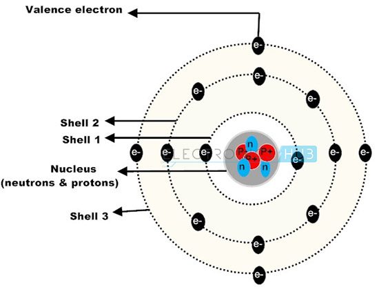
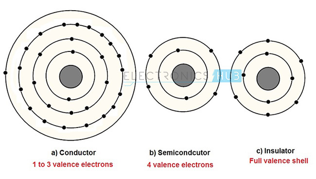
Hence great amount of external energy is required to make the electrons free so that the electricity is produced. Generally the materials which are not having free electrons in the outermost cell are called as insulators. Typically insulators have five to seven valence electrons in its valance shell. In other hand materials with one valence electron requires a little energy to free the electrons, so that the current is produced and the materials are called as conductors. Typically conductors have two or three valence electrons. These good conductors include silver, copper, aluminum, gold, etc. In prior to this, materials with four valence electrons that have both conductor and insulator properties called as semiconductors.
2.Atomic stucture of solids
As from above atomic theory, the flow of electrons gives the electricity. We know that like charges repel whereas unlike charges attract. The separation the charges makes negative charges to accumulate at one terminal and positive charges to other terminal with the application of source. The current starts to flow when the path is made between these two charges. The unit of the charge is Coulomb and it has a charge of 6.25 X 10¹⁸ electrons. The external force or voltage applied causes the charge to move and the rate at which the charge flow is decided by the amount of voltage applied.

Introduction to Simple DC Circuit and Its Parameters

We know that the electricity is of two types, Alternating Current (AC) and Direct Current (DC). A circuit that deals with AC is referred to as AC circuit and a circuit with DC source is termed as DC circuit.  As of now we only discuss about DC circuit and its theory. The DC source allows the electricity or current to flow with an unvarying polarity that doesn’t change with time. A simple DC circuit is given in below figure to make the reader get aware of DC circuit components and its parameters.
3.Simple dc circuit model
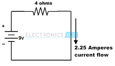
The above DC circuit consists of the voltage source and resistance with a specific current flow. So let us know about these parameters in brief.
BACK TO TOP

Electric Voltage

The potential difference between two points or voltage in an electric circuit is the amount of energy required to move a unit charge between two points. It is measured in Volts and indicated with a letter V as shown in below figure. This voltage can be either positive or negative and expressed mostly with prefixes like KV, mV, uV, etc. to denote sub-multiples of the voltage. Batteries and generators are the most commonly used DC voltage sources which can produce the DC voltage from 1V to 24V DC for functioning of general electronic circuits.
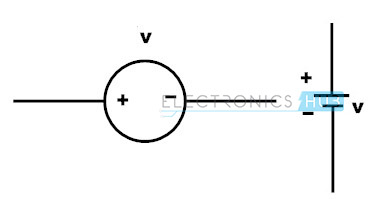
voltage symbols
BACK TO TOP

Electric Current

It is the flow of electrons or electric charge. It is measured in Amperes or simply Amps, and denoted by the letter ‘I’ or lower case i. This electric current can be direct or alternating. The Direct Current (DC) flows in a unidirectional way and generally it is produced by batteries, solar cells, thermocouples, etc. In case of AC, electric charge movement periodically changes as we can observe in case of sine wave.
4.Electric Current
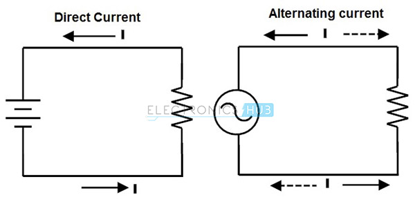
Generally in circuits the direction of current flow is indicated with a letter I or lower case I with an arrow associated with it. But this direction actually indicates the conventional current flow rather than actual electron current flow.
BACK TO TOP

Difference Between Conventional and Electron Current Flow

Electrons flow from negative terminal to positive terminal is referred as electron current flow, whereas from positive terminal to the negative terminal is referred as conventional current flow as shown in figure.
5. Difference Between Conventional and Electron Current Flow
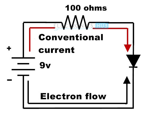
The electrons have always been repelled by the negative charge where the terminal is connected to the negative terminal of the battery and are attracted at positive terminal due to the positive charge. Hence the electrons flow from negative terminal to positive terminal is referred as electron current flow. But conventional method of assuming current flow is from positive to negative so this is referred as conventional current flow. Conventional current is indicated on many circuit diagrams and actual electron flow current is indicated in the case of describing the individual current flow. 
The conventional current flow is due to the positive charge carriers. The conventional current is measured in the opposite direction of actual electron current flow, which is due to the negative charge carriers (Electrons) therefore, conventional current is always positive. It is also measured in Amps. 
The difference of conventional and actual electron flow does not effect on any computational results and real time behavior. Most of the analyzing concepts of DC circuit results are independent of the direction of current flow. However, the conventional current is the standard and mostly follows.
BACK TO TOP

Resistance

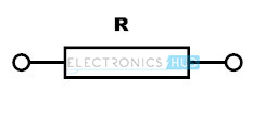
The resistance of a conducting material opposes the flow of electrons. It is measured in ohms and denoted by the Greek symbol Ω.  Depends on the resistor value in a circuit voltage applied to the circuit is decided. Thus, resistance can be defined as the voltage required for a circuit for making 1 ampere current flow. This also referred as Ohm’s law and written as R = V/I. That means if a circuit requires 200V to produce 2A current then the resistance should be 100 ohms. The resistance value is always positive. Resistors can be fixed or variable resistors as shown in figure.
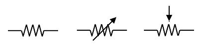
6.Resistance
BACK TO TOP

Electric power (P) and Energy

 The power is termed as the work done in a given amount of time. In electrical circuits, power is exactly equal to the product of voltage and current. Since the voltage is the work per unit charge and current is the rate at which electrons move in a circuit. The Power is measured in watts (W) and its formula is
P = I x V
According to Ohms law,
R = V/I
V= IR
Substituting in the above equation,
P = (IR) R
P = I2R
Or also, by substituting I = V/R, we can get
P= V x (V/R)
P= V2/R
These three possible formulas are used for finding the power associated with a circuit.
Electrical Energy
The rate at which electrical power consumed is generally referred as electrical energy. The energy is measured in watt-seconds as the power measured in watts and time in seconds. Often it is measured in kilowatt-hours as we can observe in our home electricity meter.
Electrical energy = power × time
BACK TO TOP

Example Problem on Electrical Parameter Calculations

Consider an electric bulb or lamp rated at 100W is connected to a supply source of 250V. Find out the current flowing to the load, the resistance of the lamp and the energy dissipated in two minutes.
7.Electrical parameter calculations
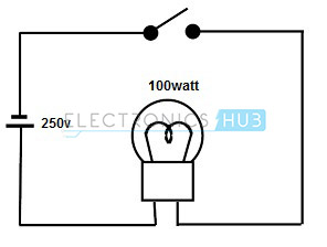
From the power formula we know that P = VI
Then the current flowing through the lamp is, I = 100 / 250
I = 0.4 A
From the ohms law,
Resistance R = V/I
R = 250/ 0.4
R = 625 ohms.
Energy dissipated,
         E = Power * time
E = V * I * t
                     = 250*0.4* (2*60)
                          = 12000 watt-second
These are the basic concepts of electrical energy which are necessary to know before dealing with any electrical circuit. With the knowledge of these basic concepts, analysis of any circuit would be made easy. Hope that we have given some key points on each parameter of an electrical circuit. Any further assistance on this concept or any comments and suggestions on this article you can comment below.
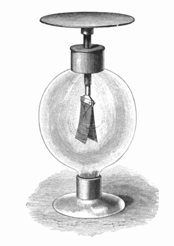
Basics of Electricity

Static Electricity- Its Perspective and Development

Mr. Theophrastus in 321BC observed that the power of amber attracts straws, dry leaves after it has been rubbed with a woolen cloth. This was the first observation of electricity and was the first recorded experiment.
Later in 1600 BC, Dr.Gilbert discovered that this attraction could be excited in many other substances besides amber. He is considered as the founder of the Electrical science.
Mr.Otto Guericke invented the first electrical machine in the year 1674. He made it by utilizing a ball of sulphur fixing it on a spindle to turn it with a handle. A friction was created by pressing the ball with a finger or hand. This machine first produced the electric spark with sound. This turned the science to make wonders to originate a new science. In this experiment, it was also observed that the ball which was excited and charged for a short time attraction will be repelled by the same object.
Sir Isaac Newton in 1675 constructed the same experiment done by Mr.Otto Guericke with some changes. Sir Newton used a glass globe and this globe produced the sparks of ½ inch and could feel them with the finger placing on it.
Later Mr. Stephen Grey in 1720 further developed that the electricity may be conveyed from the machine to the body by a wire or wet thread at a considerable distance.
In the year 1733, Mr.M.Dufay further experimented and found that if the body is kept on a stand made up of glass rods could be excited if the glass rods kept dry. In this experiment, it was also conferred that there are two kinds of electricity one which was excited by that of glass and the other excited by resin, silks etc.
Later in 1736, the Newton’s experiment improved by Professor Winckler. He utilized the horse hair covered with silk cloth instead of using the fingers or hand to rub the glass ball. In 1738 Professor Boze discovered that keeping a tube of metal can collect this electricity. It was also found that the electricity will disappear if there are sharp edges or points on this metal conductor.
Dr.Grey made several trails with different kinds of matter and discovered that some bodies will have the power to conduct electricity and some of them will not.
With all the experiments, the discovery of an electrical machine has been done with the observations, improvements and innovative developments done by these scientists with individual or combined efforts. But the amount of power produced is in small quantity. There is an effort of several scientific investigators who are responsible for inventing the great Leyden’s jar. Over a period of time with many improvements and developments this led to a great product called ‘battery’.

Static Electricity

Static electricity is the subject which deals with the study of electric charges at rest.
Recalling the above experiments done by or tried by the ancient eminent scientists, a spark or sparks have been produced with the help of glass, felt or with some other material. In all of these cases the movement of electron is responsible for this phenomenon. As per this elementary electro-static behavior, the entire process is the movement of electrons from one body to the other, thereby electrically charging of these bodies. One of the bodies will be charged positively (deficiency of electrons) and the other one negatively (excess of electrons).

Properties of the Electrical Bodies

Recalling the experiment of Mr. Dufay, two glass rods fixing on wooden stand as shown in the figure with a crossbar on them.

From the center of the crossbar a wire strip should be suspended by a silk thread, so that the wire strip will be able to move freely in a horizontal plane like a compass needle. A silk handkerchief is also needed to excite the glass rods. The experiment has to be in a warm dry room.
Now, after rubbing the glass rods briskly with the handkerchief, (it is better if two people with two handkerchiefs do the experiment) placing one at the stirred up and holding the other at the rubbed end of the wire strip. It will be observed that if the two glass rods are taken, a strong repulsion will take place and if one glass rod taken, an attraction will take place.
So, it can be concluded that similar electrifications will repel each other and unlike electrifications attracts. For this reason there exist two kinds of electricity:  (+) and (-) electricity, the electricity of the glass will be +ve electricity. By adding equal quantities of the glass electricity is zero. This resembles an algebraic sum of + and – which is equal to zero. The same experiment can be carried out by replacing the wire strip with a feather. The feather will be attracted to the rods.
Like the above experiment if the one end of the glass rod is electrified it remains for a considerable time keeping the other end un-electrified. In the same way, if one end of a metal rod is electrified, it will be distributed along the length of the rod and if the other end is connected to ground, it vanishes.

Gold Leaf Electroscope

This is the oldest instrument used to detect and determines the electrification.
Gold leaf electroscope
Image Resource Link: upload.wikimedia.org/wikipedia/commons/b/b3/Gold_leaf_electroscope_1869.png
As shown in the figure, two gold leaves will be hanged (fixed one side) and attached to a metal rod which was fixed to a brass plate through a hole placed in a glass shade. When an electric body was placed on this plate, a portion of the electricity will pass through the gold leaves charging them to repel each other.  This is the measure of the charge. This is a very sensitive instrument used to detect small quantities of the electricity.

Electro-static Induction

When a charged body is placed near another body without any physical contact between them, the second body will get electrified. The charge will exist on the other body till the charged body was present near to it, but as soon as the charged body is withdrawn the charge on the second body will disappear. This is called as electrification by induction. For example, if we rub the both hands together and place it on the above gold leaf electroscope, the gold leaves will be repelled, but as soon we remove our hands from the plate of the Gold leaf electroscope, the leaves will come to normal position.

Faraday’s Ice Pail Experiment

A charged sphere was placed into a hollow cylinder which was on the plate of the electroscope. The gold leaves spread apart till the sphere is in touch position; the leaves retained the original position as soon as the ball is removed.
This shows that
  • Equal and opposite charges will be produced by induction.
  • The charge cannot reside inside the hollow cylinder.

Laws of Electrical Forces

The force of attraction or repulsion between two electrified bodies varies inversely to the square of their distance apart where the body sizes are very small compared with their distance.

Electric Field and Potential:

An electric field is a region of space in which electric charges activated by electric forces.
The basic unit of electric charge is the coulomb.
Like gravitation and magnetic fields the electric field strength is measured in terms of force on a unit positive charge.
Electric field strength is defined as the force acting on one coulomb of positive charge at that point. The direction of the field will be in the direction of the positive charge movement.
Breakdown field strength is the field strength which causes the insulator to break down. The breakdown field strength of air is 3 x10⁶ volts/meter which limits the maximum potential of the conductor. Beyond this point corona discharge will occur.

Electrical Potential Difference

This is analogous to natural potential energy. A mass lifted against gravitational force in the gravitational field will be given potential energy. In the same way a charge can be given electrical potential energy by being moved against the force excited on it in an electric field.
The volt is defined as the potential difference between two points such that one joule of work is done if one coulomb of positive charge is moved from one point to the other.
The change in electrical energy is W of a charge q when moved with a potential difference of one volt is given by
W = qV
The electric potential at a point is defined as the work done for moving or bringing a unit of positive charge from infinity to the point.

Electric Circuits

An electric circuit is a closed path which allows the electrons to flow through it continuously. If the circuit is broken, then the current flow cannot occur through it. The location of a break in the circuit is not a matter. A break, anywhere in the circuit prevents the flow of current through the circuit.

Voltage and Current

The electric current is the rate of flow of charge. The coulomb is the practical unit measurement of electric charge in MKS systems. One unit of charge carries 6.28 x10¹⁸ electrons. So, the rate of charge transfer of one coulomb per second is called ‘ampere’.
Current I = Q/t
Where Q is charge and measured in coulombs,
t is time and it measured in seconds.
If the electron flow is not steady or moving in a non-uniform motion this ampere can be written as
Instantaneous current I = rate of change of average charge (coulombs) = dq/dt
In the same way we can say the net charge of current Q = ∫ i dt which is the integration of current.
Example-1:
A charge of 4000 coulombs passes a point P in electric circuit for half an hour. What is the average current flow?
I = Q/t = 4000/1800 = 2.2 coulombs/sec; t = 30 mins = 30×60 = 1800 sec
Example-2:
The observed current flow in the circuit is 100mA. How much charge is transferred in 5 minutes?
Q = I x t = (100/1000) x (5 x 60) = 30 coulombs
Example-3:
Typical values of copper are
n = 8.5 x 1028 m-3
e = 1.6 x 10⁻¹⁹C
I = 10 amps
A = 10-6 m2
the velocity of charges
v = I/A.n.e = 10 / (10-6 x 8.5 x 1028 x 1.6 x 10-19) = 7.3 x 10⁻³ m/s.

Electric Voltage:

It must be noted that an energy source is required to introduce the energy into the system. This energy source acts on the charge carriers, giving rise to current. Some of these sources are battery cells, generators, fuel cells and solar cells. That means a source will have the power to generate the electro-motive-force (emf). The emf is defined as the source of energy which can deliver the power to pass the charge through the source to form an electrical circuit. The unit of emf is volt.
Vab= W / Q
where
Vab is the potential difference in volts between points a and b
Q = amount of charge in coulombs moving from a to b
W = energy level difference of the charge as it moves from a to b.
The energy will be measured in Joules. So, 1 joule of energy is required to move 1 coulomb of charge for getting 1 volt of voltage.

Resistance

In the electric circuit whatever may be the source of the energy it was connected, the electrons will flow through the circuit elements where the electric current will take place. The circuit elements are mainly made of solids and the electrons will flow through them. The solids will contain different structures of atoms and while the electrons travelling through these elements; they will collide with the atoms and molecules. These collisions affect the flow of electrons because of the resistance offered by the atoms. This resistance differs from material to the material and the flow of electrons depends on the property of the material which was in the circuit. Hence, the resistance is the property of that particular material which opposes the flow of electrons. The device which is having the property of electrons opposition as the main property is called as “Resistor”. The symbol of the resistor is given below.
3. Resistance
Unit of Resistance is ohm and it is designated with a letter ’Ω’
A resistance of one ohm in a particular wire or material is that if it develops 0.24 calories of heat when one ampere of current flows through it for 1 second.

Ohm’s Law:

In the year 1827, George Simon Ohm, a scientist observed that the electrical direct current (D.C.) flowing through a metallic conductor varies directly with the voltage applied to it. This is called the ohm’s law. According to the law
Current, I = [Voltage (V)/Resistance (R)] in Amperes (A).
Therefore
Resistance R = (V/I) ohms

Conductance:

The conductance of the material is the converse of the resistive property of that material. It means the conductance is the reciprocal of the resistance in the mathematical form. The symbol of conductance is G and is equal to 1/R.
The unit of conductance is siemen and will be denoted as ‘℧’.
If 1 volt of the voltage is applied to a conductor and if 1 ampere current flows through it for a second, the material or wire is having a conductance of 1 mho.

Voltage and Current in a Practical Circuit

Any practical electrical current source will have an internal resistance. Depending upon the origin of source generation this internal resistance varies. For example in a generator the internal resistance is the resistance of the copper windings. In practice it cannot be removed. The potential difference between the two terminals of the voltage source when the source (E) is idle never matches with that of the potential difference when the source is delivering the electric current (V). This is the result of the internal resistance and difference of these potential differences is called as lost volts (E – V). Obviously this is the voltage drop of the internal resistance (E –V = Ir)
4. Voltage and current in a practical circuit
Example:
If the internal resistance of the battery is 1 ohm, Calculate
a) Voltage across the resistor R3,
b) current through R1,
c) lost volts as per the following circuit.
5. Example
Sol:
The resultant resistance of R1, Rwill be Ro
Ro = (R1 x R2) / (R1 + R2) = 2/3 ohms
The total resistance = Ro +R3 + battery internal resistance = 2/3 + 1(1/3) + 1 = 3 ohms.
Current from the battery = 6/3 = 2 amps
a) Voltage across the resistor R3 = 2 x 1(1/3) = 2(2/3) V
b) Voltage across Ro = 2 x 2/3 = 4/3 = 1(1/3) V,
Current through R1 = V/R1 = (4/3)/2 =2/3 A
c) Lost volts= I x r = 2 x 1 = 2 V
Finally by cross checking: E = Vr + VR1 + VR3 = 2 + 1(1/3) +2(2/3) = 6 V.